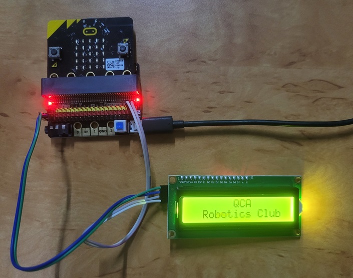
The micro:bit as you all know has a built-in 5 x 5 grid LED screen which can display and represent text, numbers and shape images by controlling each LED to “on” or “off” state. This is well and good and benefits the portability, friendliness and usefulness of the device for beginners. But what if you want a better display, such as a LCD to your project?
A standard LCD can be incorporated in your project but requires over ten connections, which creates a bit of a problem if you have limited availability of free GPIO pins.
The Solution: I2C LCD
An I2C (Inter-Integrated Circuit) LCD simplifies connection to your circuit. A standard LCD has a parallel data bus while an I2C has a serial data bus. Having a serial bus has its advantages and simplifies the connection requirement by utilizing only two data pins to control the LCD.
An I2C bus consists of two signals: Serial DAta signal (SDA) and the Serial CLock signal (SCL). The SDA pin is where data is sent in between the LCD module and the micro:bit while the SCL pin is where synchronization of pulse clock signal takes place between transmitter and receiver.
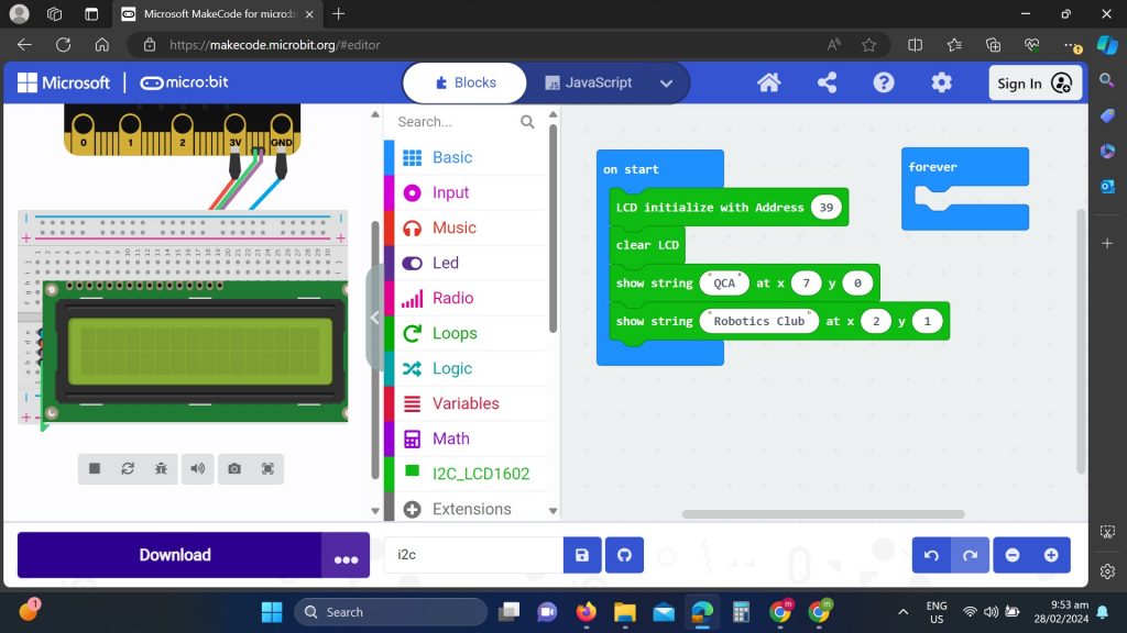
An I2C is usually an add-on circuit package located at the back of an LCD module. The connection is usually straight forward as you connect the LCD’s SDA pin to the micro:bit’s SDA pin P20 and the LCD’s SCL pin to the micro:bit’s SCL pin P19. Another 2 pins are available in the I2C module and corresponds to the power supply (Vcc) and Ground (GND) connection.
Each I2C circuit module has an address for identification and communication. The two common addressed being used are hexadecimal (hex) address 0x27 which is equivalent to decimal (39) and address 0x3F or decimal (63). We use either of this address to initiate communication with the micro:bit in our program.
The two most common LCD module available in the market are 2 x16 LCD and 4 x 20 LCD. The 2×16 means the first digit 2, in this case represents two vertical lines and 16 means you can have sixteen characters in a line. The LCD displays each character through a matrix grid of 5×8 pixels. These pixels can display standard text, numbers, or special characters and can also be programmed to display custom characters.
Connections
Connecting an LCD module display to the micro:bit is straight forward. Just connect the corresponding SCL and SDA pins on both device and connect the LCD module to a 5v DC power source. Remember that micro:bit only runs on 3v, so you need a battery pack or an GPIO interface that has a built-in 5v DC source such as the KittenBot IOBit v2.0.

Programming an I2C LCD Display
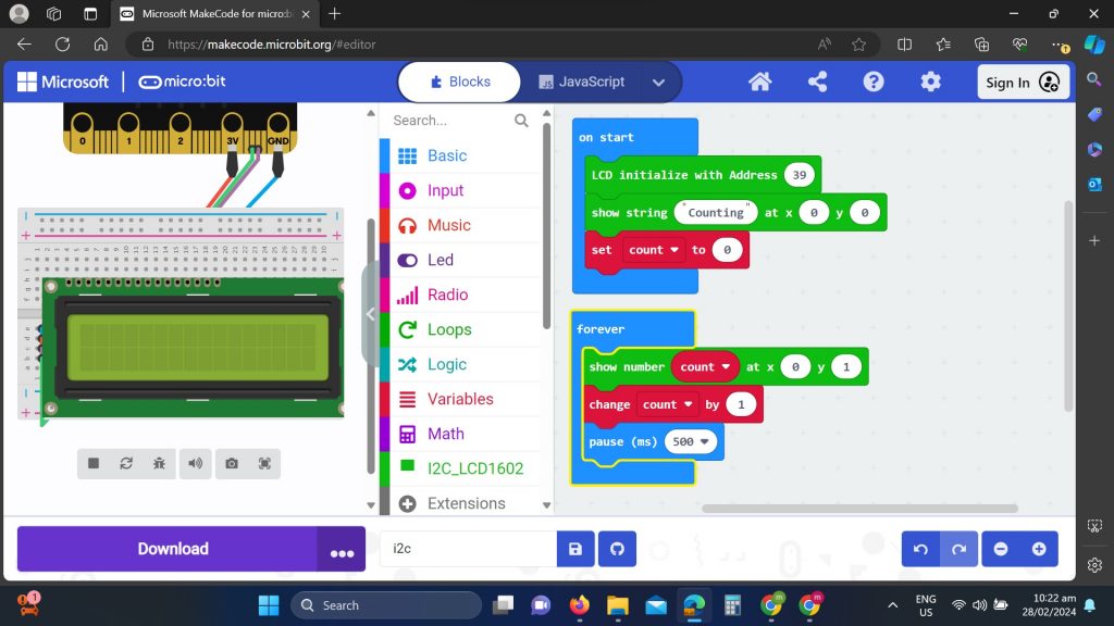
Before we can use the LCD display module, we need to load the i2cLCD1602 display function by adding the Extension under the Tool Box Section of Makecode.


Notes: Use variable function for code sample 2 (counting to infinity)
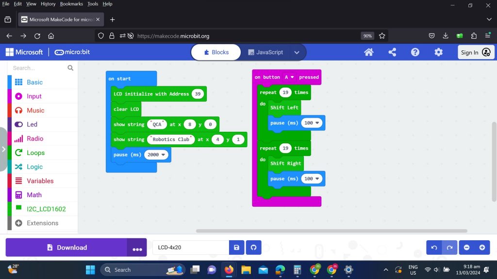
We can also use a 20×4 LCD display module using the same i2cLCD1602 display function but obviously the code for the display function is not optimized for a 20×40 display – but it should work for some basic functions. Currently (March 2024), I am not aware of any extensions specific for the 20×4 LCD display module. There is a code on Github if you are adventurist enough to convert the source code to hex code:
https://github.com/calliope-net/lcd-20×4?tab=readme-ov-file#readme
Scrolling text to the left and right is possible using Shift Left and Shift Right functions. See example below:

Note: Sample above makes use of 20×4 LCD module, adjust your code if you are using a 16×2 LCD module
