Controlling External LED with Microbit
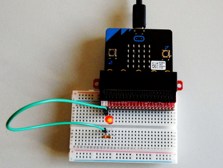
To control an external LED using the microbit, one has to be careful with the right orientation of the LED pins when supplying power through it. The longer pin of the LED is the anode and should be connected to a positive source. On the microbit, these should be the GPIO pins labeled 0, 1, and 2 (The GPIO 3V will only supply 3 volts to the LED but you can’t control it.). The shorter pin of the LED is the cathode and should be connected to the Ground (GND) GPIO pin.
It is advisable to add a resistor in series with the LED to limit the current flowing through it and avoid burning the LED.

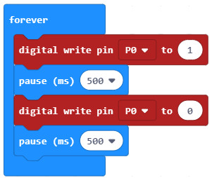
In MS Make Code, we control the LED by using the digital write pin block from the Advanced – Pins section of the toolbox block menu. The code to lit and dim the LED is shown below:

Attaching a piezo speaker and playing some music with the MIcrobit
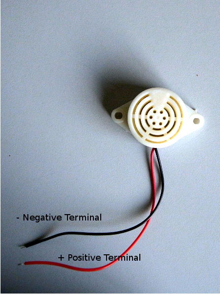
It is relatively easy to produce tones and music with the BBC Microbit. This can be easily done by attaching a piezo speaker on pin 0 (positive terminal of the speaker) and GND of the GPIO. If you mistakenly connect the speaker terminals in reverse, you won’t hear an audio.

In MS Make Code, we make use of the blocks in the Music menu blocks. Our example will play a ringtone using the start melody block on start only once. Feel free to try the other music blocks and have fun.

