What is the difference between digital read pin vs analog read pin?
We use digital read pin when we want to read a digital (0 or 1) signal from a pin in the microbit board. The general purpose input and output (GPIO) pins are P0, P1 and P2. Pins P3, P4, P6, P7, P9, and P10 can also be used provided you do not use the onboard LED screen such as scrolling a text message because the pins are shared with the onboard LED.
For reference, please consult the official microbit external connection pins page at https://microbit.org/guide/hardware/pins/.
We use the analog read pin when we want to read an analog signal source and that signal will be converted to values from 0 through 1023. To have an idea on what values are being sent by a sensor to your microbit (for reference purposes), just assign a variable and show that variable directly to the onboard LED screen. The example code shows how this is done:

GPIO Shared Pins Usage
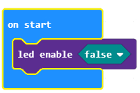
As mentioned above, pins P3, P4, P6, P7, P9, and P10 shares the connection with the onboard LED matrix display and also it’s associated ambient light sensing mode. To avoid unwanted signal stray when using these pins as input, disable the on-board LED screen by invoking the block Led Enabled False on start of your program code.

Playing Sounds
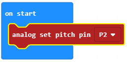
By default, microbit will play a sound through pin P0. In order to use another pin, such as pin P2, to play a sound, you need to use the Analog Set Pitch Pin block upon on start.

