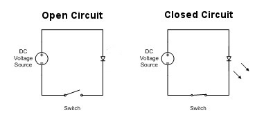
It’s important that we need to learn the basics of electronics and have a solid foundation on how things work before we move further on our micro:bit learning adventure. Most of what we are going to make are made up of a circuit. To create a circuit, it must have three basic elements: a voltage source, conductive path and a load.
A voltage source, such as a battery, is needed in order to cause the current to flow through the circuit. For the current to flow, a conductive path needs to be present. Finally, a LED, an electric motor or any electrical device that converts electrical energy into light, heat, sound or useful motion constitutes a load on the circuit.

A closed circuit means a complete electrical connection is accomplished within a closed loop of conductive components which current can flow or circulate. In contrast, if there is a break in the flow of electricity, this is known as an open circuit.
Current, Voltage, Resistance and Ohm’s Law
In any closed circuit, current flow along its conductive path. There are two types of currents: alternating current (AC) and direct current (DC). DC is used for electronic circuits and normally flows in one direction. Case in point, a battery has two ends and has a positive and negative pole. In order for current to flow correctly, the ends of the poles needs to be connected properly. That is why when you place a battery in the wrong direction like inside a wall clock or toy, the device would not work. Current is usually measured in terms of amperes or A.
Voltage is what makes electric charges move. It is the pressure that causes current to move through a conductive path or loop to do work such as illuminating a light. You measure voltage as a voltage difference between two points and is represented by the letter V.
Resistance is the opposition of the flow of current in an electronic circuit. It is measured in ohms and represented by the symbol omega or letter R.

The relationship between current, voltage and resistance is called Ohm’s Law. To best illustrate their relation, imagine a pipe filled with water. The amount of water running inside the pipe represents the current. Then imagine that somewhere along the pipe there is a clog that prevents the water from flowing freely. The clog represents resistance. The water pressure on one side of the clog would be much higher than the other side. The difference in pressure between this two points is equivalent to voltage.
Ohm’s Law is very useful in electronics. It is represented by the formula:

Common Electronic Components
Resistors

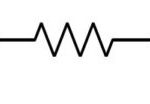
Resistors are commonly used in electronic projects. Resistors limit the flow of current. They are normally placed together with other electronic components to control the amount of current flowing in the circuit. For example, a typical LED operates at around 2 to 3.5 volts and needs a 10 to 20 mA of current to operate correctly. Anything higher than these values would probably destroy and burn the LED. So, to control the current, we usually place a resistor in series with a LED.
Potentiometer

oA potentiometer is a mechanical rotary or sliding device that has a variable output resistance. It is used commonly as a means to control light, sound, heat, frequency or speed of an electrical component.
Switch

An electronic switch operates as a means to control the current flow of a circuit from on or off.
Battery

A battery is a DC source used to supply power to electronic devices. It has a positive and negative poll.
Light Emitting Diodes (LED)

A LED is a type of diode that emits light when current passes through it. It has two pins called anode and cathode that must be hooked correctly to operate. The longest pin is the anode and should be connected to a positive source. The shortest pin is the cathode and is connected to the negative source.
Piezo Speaker

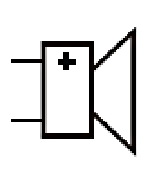
A piezo speaker is a simple device that will emit a tone when given a certain pulse from an electronic circuit. They are good enough for beep tone sounds rather than fidelity music output.
Relay

Relays are switches that open or closes a circuit electromechanically or electronically. Relays control one electrical circuit by opening and closing contacts in another circuit.
